
Monday, November 2, 2009
Electronic Ballast Output and Drive Waveforms (Torroid).
Electronic Ballast Output and Drive Waveforms (Torroid).


DC AC CFL Inverter Schematics
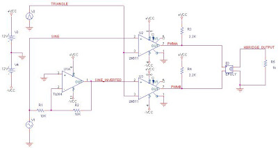
Battery powdred CFL Inverters are widly used in solar lighting emergency lighting and automobile lighting. The schematics we are working out is a popular DC AC inverter widly used in general battery powdered applications as well as used in Electronics Ballast where Line Voltage is Less(110V AC as in US). This basicaly push pull current fed parallel resonant self oscilating inverter. The inductor L1,L2 and reflected impedance of C1 forms LC tank circuit.
L4 will source current while giving maximum impedance to higher harmonics. R2, L5, L6 provides base drive. You can note primary rms voltage is 1.1 times of battery voltage because L4 act as boost inductor. Both switches are working in ZVS. Out put is pure sine wave. Load power dissipation is 9W. But Tank circulating power is arround 80W.

L4 will source current while giving maximum impedance to higher harmonics. R2, L5, L6 provides base drive. You can note primary rms voltage is 1.1 times of battery voltage because L4 act as boost inductor. Both switches are working in ZVS. Out put is pure sine wave. Load power dissipation is 9W. But Tank circulating power is arround 80W.


Wednesday, October 7, 2009


Sunday, August 23, 2009

Three Phase Six Pulse Converter Controll Circuit
Circuit diagram of three phase six pulse converter with current and voltage feedback is given above. Out put stage is capable of driving 250 amps 1800V SCR. If we reduce gate series resistor to 22 ohm we can drive 800 amps SCR. This converter is well suited for power level upto 250 KW


Saturday, August 22, 2009
Solar Panel Price
panel price
$1.85/W solar panels! Free Solar Panel Survey
www.ecobusinesslinks.com/solar_panels.htm
http://www.atensolar.com/14.html
$1.85/W solar panels! Free Solar Panel Survey
www.ecobusinesslinks.com/solar_panels.htm
http://www.atensolar.com/14.html
Friday, June 12, 2009
Electronic Earth Leakage Circuit Breaker

Differential CT is used to sense earth leakage current. Out put current of Differiantial CT will be difference of Phase current and Neutral current divided by turns ratio. This current is fed to current to voltage converter. One variable resistor is provided in the fee back path to audjest sensitivity. This signal is full wave rectified and given to relay driving circuit with a small delay.
SCR is used as relay drive for latched operation. Push to on switch is used for resetting the circuit. Test switch is used to check the working of the circuit by creating a artificial leackage current of 20mA. Another good referance design from Fairchild Semiconductor http://www.fairchildsemi.com/ds/RV%2FRV4141A.pdf
Sunday, June 7, 2009
Electronic Transformer
Matix converter can be used with a high frequency ac link to make low frequency transformer.
The circuit presented here uses MOSFET as switches and EE70 ferrite core transformer as AC link. Transformation ratio is directly prepotional to turns ratio of EE70. If EE 70 have 1:1 turns ratio the curcuit will act as 1:1 isolation transformer. The main adventage of this topology is its low frequency response. We can use this electronics transformer DC to 200Hz.

Saturday, June 6, 2009
Multi Level Inverter
Multi Level Inverters are used to produce fine pwm wave forms with muliple voltage steps. It uses one or more power sources and multiple power switches. Main adventage of multilevel inverter is low switching component at output which will reduce the output filter components.
Multilevel inverters have very low switching loss but conduction losses are high. Another adventage is reduced voltage requirment of switching devices. The circuit given below is a three level inverter.The power supply is + - 400V connected as dual polarity bus ie 800V. Four 600V IGBT switches are connected in series and center point is taken as output. The levels are defined by shifting triangle wave above and belo GND (0V). 6V amplitude 50 hz sinewave is the input signal which is reproduced as 385V at output.Out put pwm have three levels 0V +400V and
-400V
Circuit of Multi Level Inverter
 Input Sine Wave and level shifted Triangle Wave

 PWM Out Put and Final Out Put

Have nice day
Friday, March 27, 2009
Regenerative Loading of Inverters

This is the popular loading method for high power inverters. The inverter is configured as current mode inverter and referance sine wave is generated from utility.The referance amlitude is audjested for variying load.If we load 100KVA online ups full load we need only the power loss which will happen in UPS.Ie if efficiency of ups is 95% we need only 5KW from line to load full 100KW.
Wednesday, March 11, 2009
APC UPS Circuits
for APC UPS circuits
http://www.eserviceinfo.com/equipment_mfg/APC_23.html
for service manuals
http://www.eserviceinfo.com/browse.php
http://www.eserviceinfo.com/equipment_mfg/APC_23.html
for service manuals
http://www.eserviceinfo.com/browse.php
Sunday, March 8, 2009
Unipolar PWM
Uni Polar PWM

sine triangle and output

Basic circuit of unipolar sinewave PWM
sine wave referance triangle wave and PWM waveforms

Bipolar PWM
Following is the basic circuit of bipolar PWM and its waveforms
circuit diagram
Waveforms of this circuit
triangle wave sine wave and PWM output


Saturday, March 7, 2009

Monday, February 9, 2009


Sunday, February 8, 2009
Active Power Factor Correction
Useful links on Active Power Factor Correction
Power Factor Correction Handbookhttp://www.onsemi.com/pub/Collateral/HBD853-D.PDF
UC3854 Controlled Power Factor Correction Circuit Designhttp://www.ti.com/litv/pdf/slua144
Optimizing Performance in UC3854 Power Factor Correction Applicationshttp://www.ti.com/litv/pdf/slua172
UC3854A and UC3854B Advanced Power Factor Correction Control ICs (Rev. A)http://www.ti.com/litv/pdf/slua177a
Improved Power MOSFETS Boost Efficiency IN A 3.5kw Single Phase PFChttp://www.microsemi.com/micnotes/APT0101.pdf
Optimizing the Design of 3.5kw Single-MOSFET Power Factor Correctorshttp://www.microsemi.com/micnotes/APT9901.pdf


Battery Powered CFL Inverter Flyback
Circuit of popular Battery powered CFL inverter using flyback out put stage.
It is the lowest component count and coast but will fail at no load (tube disconnected).
It is the lowest component count and coast but will fail at no load (tube disconnected).
Thursday, February 5, 2009
DC AC CFL Inverter Push Pull
Parallel resonant current fed push pull inverter for battery powered lighting applications. It uses capacitor C3 for preheating and electrostatic shield for tube starting.
DC AC CFL Inverter with preheating
Parallel resonant current fed push pull inverter with preheated staring with out the help of electrostatic shield for battery powered lighting applications.No load protection is also provided. 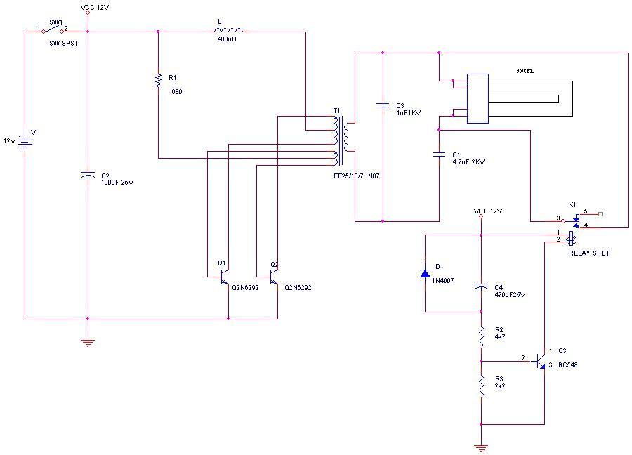
Wednesday, January 28, 2009
AC voltage sensing circuit

This circuit is used to sense ac line voltage with out using transformer and gives very low leackage current while circuit ground can be connected any potential.test
Thursday, January 22, 2009
Subscribe to:
Posts (Atom)